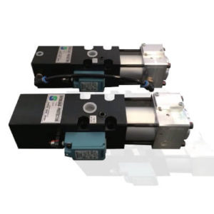
Description
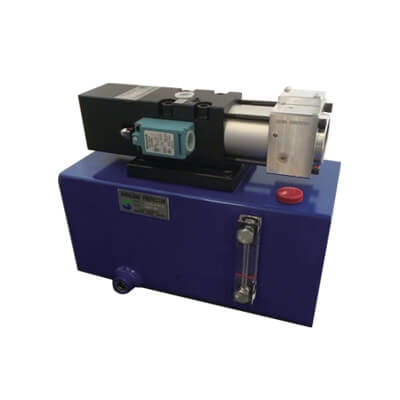
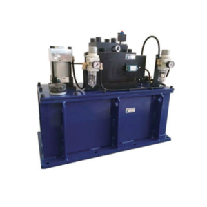
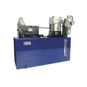
OLP – INTERGRATED OVERLOAD PROTECTOR WITH OIL TANK

| ① | Overload protector model | ||||||
| ② | Manual relief valve its position No symbol : Without Manual relief valve X: Manual relief valve and overload protector along the left-right direction installation XA: Manual relief valve and overload protector along the anterior-posterior direction installation |
||||||
| ③ | Tank capacity | ||||||
| ④ | With or without air supply solenoid valve and air pressure reducing valve No symbol : without it V: With it |
||||||
| ⑤ | supply valve Voltage
|
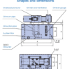
4{/1 Unit: mm
|
Tank capacity |
A |
B |
C |
D |
E |
F |
G |
H |
J |
Applicable To Cylinder Capacity
|
| 2.5L | 250 | 60 | 280 | 120 | 60 | 20 | 142 | 120 | 13 | <0.58L |
| 3.9L | 290 | 70 | 320 | 120 | 60 | 18 | 142 | 150 | 12 | <1.4L |
| 5L | 290 | 90 | 320 | 150 | 90 | 20 | 172 | 150 | 13 | <1.5L |
| 6.3L | 350 | 100 | 380 | 140 | 90 | 18 | 172 | 160 | 12 | <2.9L |
| 8L | 320 | 120 | 350 | 180 | 120 | 20 | 202 | 180 | 13 | <3.0L |
| 10L | 400 | 120 | 430 | 180 | 120 | 20 | 202 | 180 | 13 | <3.8L |
| 1Jr | 470 | 140 | 500 | 200 | 140 | 20 | 222 | 200 | 13 | <7.1L |
| 35 | 570 | 220 | 600 | 250 | 190 | 20 | 272 | 280 | 13 | <20.6L |

